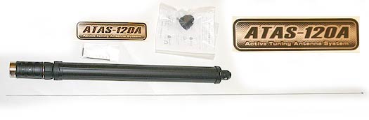
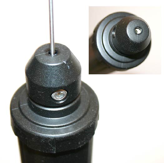
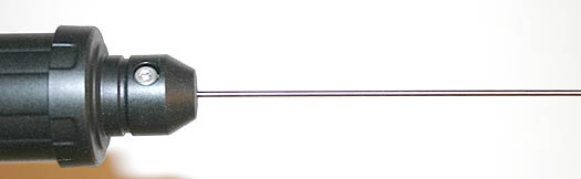
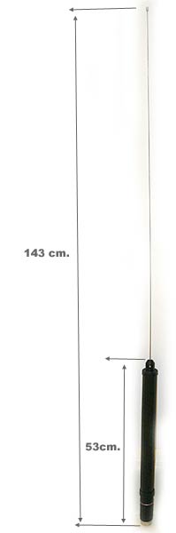
ACTIVE TUNING ANTENNA SYSTEM (ATAS-100 / -120)
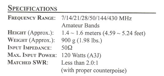
The optional ATAS-100 / -120 Active Tuning Antenna System allows you to operate in various HF bands (7/14/21/28 MHz), as well as in the 50, 144, and 430 MHz ranges. Through the microprocessor The FT-857 incorporates the tuning mechanism control, in order to have the advantages of automatic selection. .
Before it can begin operating, you must notify the FT-857 microprocessor that the ATAS-100 / -120 system is being used. The above is accomplished by configuring the Menu System:
1. To begin, press and hold the [FUNC] button for one second to activate the system
of the Menu.
2. After moving the SELECT knob and entering Mode No-001 [EXT MENU], proceed to turn the Tuning control to make this parameter effective and enable the expanded mode of said menu.
3. Move the SELECT knob below to enter Instruction N0-085 [TUNER / ATAS] from the Menu. This feature originally came% u201Cable% u201D from the factory. Therefore, turn the TUNING knob to now change this parameter to% u201CATAS (ALL)% u201D, if you are using the antenna system for all bands (it is necessary to connect an external duplexer to combine the two antenna ports, so that you can use this device in all of them). Or else, choose parameter% u201CATAS (HF & 50)% u201D, if you are using the
ATAS-100 / -120 system in the range between 7 and 50 MHz with a two-band VHF / UHF antenna independently connected to the 144/430 MHz antenna port. If you are using the ATAS-100 / -120 system in HF bands only, with a two-band VHF / UHF antenna independently connected to the 144/430 MHz antenna port (except
50 MHz), then select the% u201CATAS (HF)% u201D option.
4. Finally, press the [FUNC] button in order to store this new instruction and continue using the radio in the usual way.
Automatic tuning
1. Press the [FUNC] button and then rotate the SELECT knob as many times as necessary until the Multi Function Column% u201Ck% u201D [TUNE, DOWN, UP] appears on the display.
2. Press the [A] (TUNE) key to activate the ATAS-100 / -120 system (the above only opens the current flow to the antenna at this point, but does not start retuning). In such a case, the% u201CATAS% u201D icon lights up on the radio's LCD screen.
3. At this stage, press the [A] (TUNE) key firmly for one second to start tuning with the ATAS-100 / -120 system. This will automatically trigger the transmitter, generate a carrier signal, and adjust the antenna length for the best standing wave ratio (SWR) that can be achieved.
4. If the microprocessor determines that the antenna length differs diametrically from the optimum value, then no carrier will be emitted. On the contrary, in the reception mode, the antenna will be collected until reaching the maximum or minimum extension that it has (which could take
up to a minute). While this occurs, do not press the [A] (TUNE) key again.
Once the ATAS-100 / -120 system reaches its minimum extension, the transceiver will initiate automatic tuning and disconnect the transmitter as soon as a satisfactory standing wave ratio is obtained.
5. In the 144 MHz and 430 MHz bands, the ATAS-100 / -120 system does not need to undergo the tuning process, since a satisfactory standing wave ratio is obtained at the time the antenna is fully retracted.
6. When you want to disable the ATAS-100 / -120 system, press [A] (TUNE) once more so that the% u201C% u201D icon disappears around the% u201CATAS% u201D indication in the display. when the ATAS-100/120 antenna system is retracted to its minimum extent, it does not automatically disconnect on the spot; if not, your motor may continue to latch up to 30 seconds later, once the timer expires. A clutch mechanism prevents the antenna from being damaged during the process, the occurrence of which is also perfectly normal for the system.
Manual tuning
Under certain circumstances, it is possible to slightly improve the standing wave ratio by adjusting the position of the antenna manually. This adjustment might be necessary to operate in such bands as the 40 meter band, for example, where the factor% u201CQ% u201D of the ATAS-100 / -120 system is high, thus producing a narrow resonance margin.
To tune the ATAS-100 / -120 system manually, first retrieve the Multiple Column
Functions% u201Ck% u201D [TUNE, DOWN, UP] and then press firmly the microphone PTT switch.
With the transceiver in% u201CTransmission% u201D mode, press the [C] (UP) key (to raise the antenna) or the [B] (DWN) key (to lower it). While holding down either of these two keys, the FT-857 generates a carrier, which allows you to view the top scale of the radius meter to determine when the reading on that instrument reaches its lowest value. Once that level is reached, release the [C] (UP) or [B] (DWN) key, just like the PTT switch, to reset the% u201CReception% u201D mode on the radio.
1) Once you have successfully adapted the impedances automatically, you should vary the frequency by at least 10 kHz before trying to pair them again. Within a ± 10 kHz window from the adaptation point, the microprocessor will ignore any command to automatically match the impedances.
2) The tuning of the antenna is achieved using a carrier of% u201COC% u201D; however, the mode indication does not change to% u201CCW% u201D (if operating from a different mode) during the process.
3) If you see a High Standing Wave Ratio% u201CHI SWR% u201D on the LCD screen, it could be due to a problem in the coax cable (a poorly made connection, for example), which would not allow you to tune properly the antenna. Replace the cable or if you prefer, lengthen the one with a few meters or feet (to eliminate the possibility of adverse% u201% u201D transformer bump occurring in the 50W cord during tuning).
4) If you are able to reach a Standing Wave Ratio less than 2: 1 through manual tuning, the FT-857 will be set to% u201 Accept% u201D said value, being able to perform the automatic tuning reset when changing band. However, if you stopped manual tuning at an inappropriate level (SWR> 2: 1), the FT-857 will not allow you to continue adjusting it.
automatically. In order to reset the ATAS-100 / -120 system parameters, press the key.
[B] (DOWN) until the antenna is fully retracted, then restart tuning
automatic according to the procedure described earlier in the manual.
5) The FT-857 can also be used with the ATAS-100 antenna model, although its tuning speed is 20% lower than that of the ATAS-120. Recommendations Relating to the Operation of ATAS-100 / -120
The information presented here will allow you to derive the maximum possible performance from the ATAS-100 / -120 Active Tuning Antenna System.
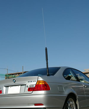
Grounding
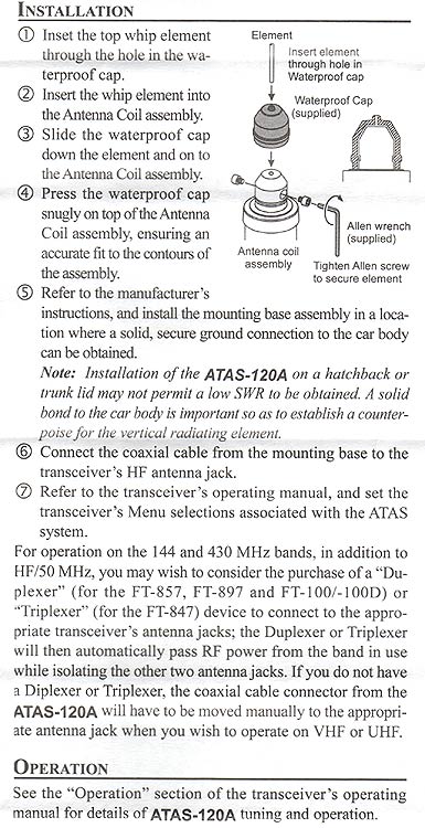
Establishing a good RF and mechanical ground connection is vital to use your ATAS-100 / -120 system (as is the case with any vertical antenna). In general, movable supports bolted to the roof of the vehicle or mechanically attached in some other way give good results. However, magnetic pedestals do not provide the ground connection of
RF necessary to achieve a good performance and therefore, it is not recommended to use them with this type of antenna.
Tuning Procedure
The impedance at the power point of the ATAS-100 / -120 system (resistance and reactance) will inevitably fluctuate within a wide range when changing bands. Sometimes the radio microprocessor will not be able to determine initially which direction (inward or outward) such an antenna system should be oriented to obtain the best Wave Ratio
Possible stationary.
In order to resolve this situation, the transceiver will order the ATAS-100 / -120 system to retract completely until it reaches its minimum or maximum extension and from there, restart the tuning process. In that case, the% u201CWAIT% u201D icon continues to be displayed on the screen even after pressing the [A] key (TUNE). If these conditions exist, do not press the key again, since the transceiver continues in reception mode while the antenna is being retracted (which may take up to a minute). Thereafter, the transmitter remains busy, while the ATAS-100 / -120 system automatically adjusts for the best possible Standing Wave Ratio.
Subsequently, the% u201CTUNE% u201D icon is no longer illuminated on the LCD screen, in which case the radio would be ready for use.
External Wattmeters
If you want to use an external wattmeter in conjunction with the transceiver and the ATAS-100 / - 120 system, please check the device with an ohmmeter before proceeding with the installation.
Make sure that there is a direct connection between the plugs of% u201CENTRADA% u201D and% u201CSALIDA% u201D of the wattmeter (zero resistance) and that there is also a completely open circuit between the central pin and the shield of the output connector of said meter . Some wattmeters use a coil or other device that short-circuits the center pin to DC ground, and it is precisely this kind of internal measurement circuit that prevents the tuning mechanism of the ATAS-100 / -120 unit from operating.
Exploitation in the Bands of 30, 17 and 12 Meters
Despite the fact that the use of the ATAS-100 / -120 antenna system is not specified for the bands indicated above and therefore, its optimal operation is not guaranteed in any of them, it is generally possible to tune said system in such bands with very good results (yes, some manual adjustment may be required). The operation of the ATAS-100 / -120 in these bands does not damage any component of the antenna, so do not be afraid to experiment, if you wish, in all of them. |