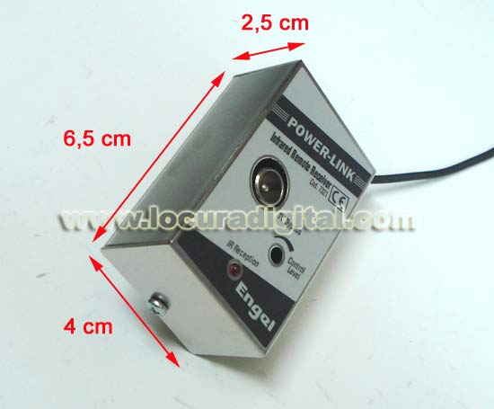
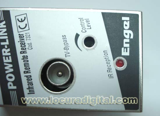
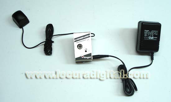
ref: MV7320 MV-7320 Power extensor Link of signal of controls by coaxial With the extensor of remote controls POWER-LINK it will be able to control fromany television set, the infrared equipment connected to another Receiving television set analogical or digital satellite, Videograbador, CATV, HIFI, etc 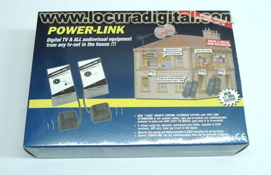
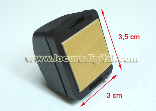
For the correct fixation of the reemisor LED on the equipment to control (fig.1A), he is advisable to interconnect reemisor and receiving according to fig1-0, arranging thecapturing "B" in a box as opposed to the controls at a distance. Before connecting sources POWER-LINK to 220V, it asegúrese that from within of the box the controls do not control equipment "E". It can connect the sources and now optimize the position of the reemisor To on the surface of equipment "E" (acting on the remote controls). Remember that elled of infrared emits and receives by the part opposed to the cable entrance (to see fig1-C). 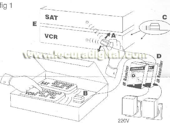
Now make the assembly of fig 2 locating the REEMISOR in the taking TV next to the equipment to control (Room1) and the RECEIVER in the taking TV of the distant television set (Room2). It is very important that capturing the B does not receive the emissions directly delled reemisor To and that after connecting to thenetwork equipment POWER-L1NK, the remote controls continuen operative as before (fig2-C vease). Now optimize the situation of the capturing B (fig2) for a correct command activity "Or" equipment to control "E". Note: He is advisable to begin this operationwith the level of the RECEIVER to maximum (fig 2-G), diminishing it DES then at an operative level without saturations and interferences. 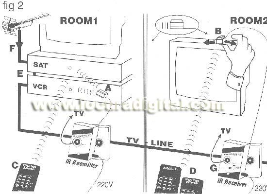
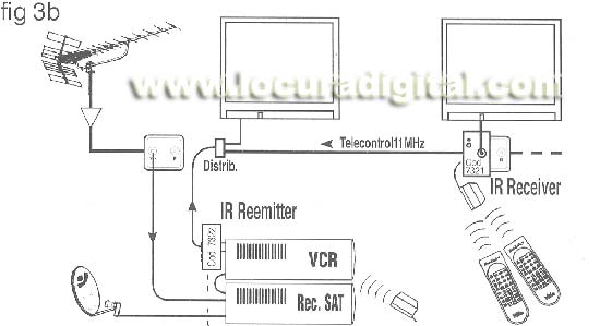
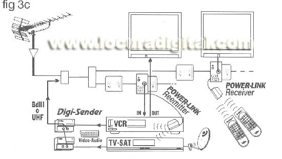
In order to receive the signal of the equipment in all the television sets, conec will haveto tar them to the head of the installation like in fig2-E or figs. á, 3b or 3c. we allowed ourselves to recommend the use to him of D1GI-SENDER I AV-SENDER (fig 3c) to make this function. 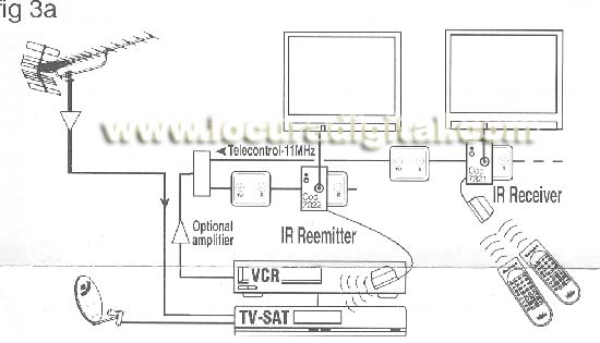
Precautions: - It tries that reemisor infrared receiver and LED correctly are oriented without obstacles to intermedios(verfig1-A and fig2-B) - Although it can put so many receivers and reemisores as it wishes, tries that the domestic walls or objects prevent the optical connections between the mall pillows of infrared. Avoid therefore that a same remote control can act simultaneamente with two receivers TO GO (fig â), that a reemisor TO GO can interact with a receiver TO GO (figAb) or that two reemisores at the same time actuen with a same equipment TO GO (fig 4c). 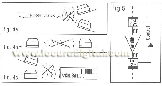
- If in some point of the installation there were some inner amplifier of step, it must have a "way of return" to the signalsof control by means of two devices 7306 (fig.5). - In case of provinentes interferences of the antenna thatproduce undesirable emissions or the low sensitivity at maximum level (fig2-G), he is advisable intercalary in the antenna lead a suppresor of espureas 7307 or 7306 (fig2-F). This device will also eliminate possible interactions with you equip external located in thesame communitarian installation. In case of doubt or persistenceof some probiema consuite to its distributor. It includes: - 1 emitter
- 1 receiver
- 2 transforming of wall
- 1 manual instructions in Spanish, ingles, frances, Italian and Portuguese 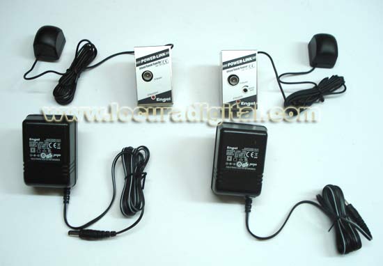
|